Protocol guide
This chapter describes the Distributed Symmetric Key Establishment (DSKE) protocol as it is implemented in this repository.
If you are not yet familiar with the concepts of quantum-safe security, Post Quantum Cryptography (PQC) or Quantum Key Distribution (QKD), it is helpful to first read the introduction: what is DSKE and what problem does it solve?.
Inspiration
Our DSKE implementation is inspired by:
-
IETF Internet Draft draft-mwag-dske-02
Distributed Symmetric Key Establishment (DSKE).
https://datatracker.ietf.org/doc/draft-mwag-dske/02/ -
Paper arXiv:2205.00615:
Distributed Symmetric Key Establishment: A scalable, quantum-proof key distribution system.
https://arxiv.org/abs/2205.00615 -
Paper arXiv:2304.13789
Composable Security of Distributed Symmetric Key Establishment Protocol.
https://arxiv.org/abs/2304.13789
We say “inspired by” because:
-
The draft and the paper only describe the general approach. They do not describe the protocol in sufficient detail for an unambiguous interoperable implementation. For example, the draft and the paper do not specify message formats or finite state machines.
-
Our implementation deviates from the draft and the paper in some aspects. Sometimes, we found it difficult to follow the details in the description. Other times, the description was clear enough, but we made a conscious decision to deviate. A list of differences between the draft/paper and this implementation is given below.
Network topology
The following figure shows the topology that we use in all of our examples and which is specified
in file dske-config.yaml:
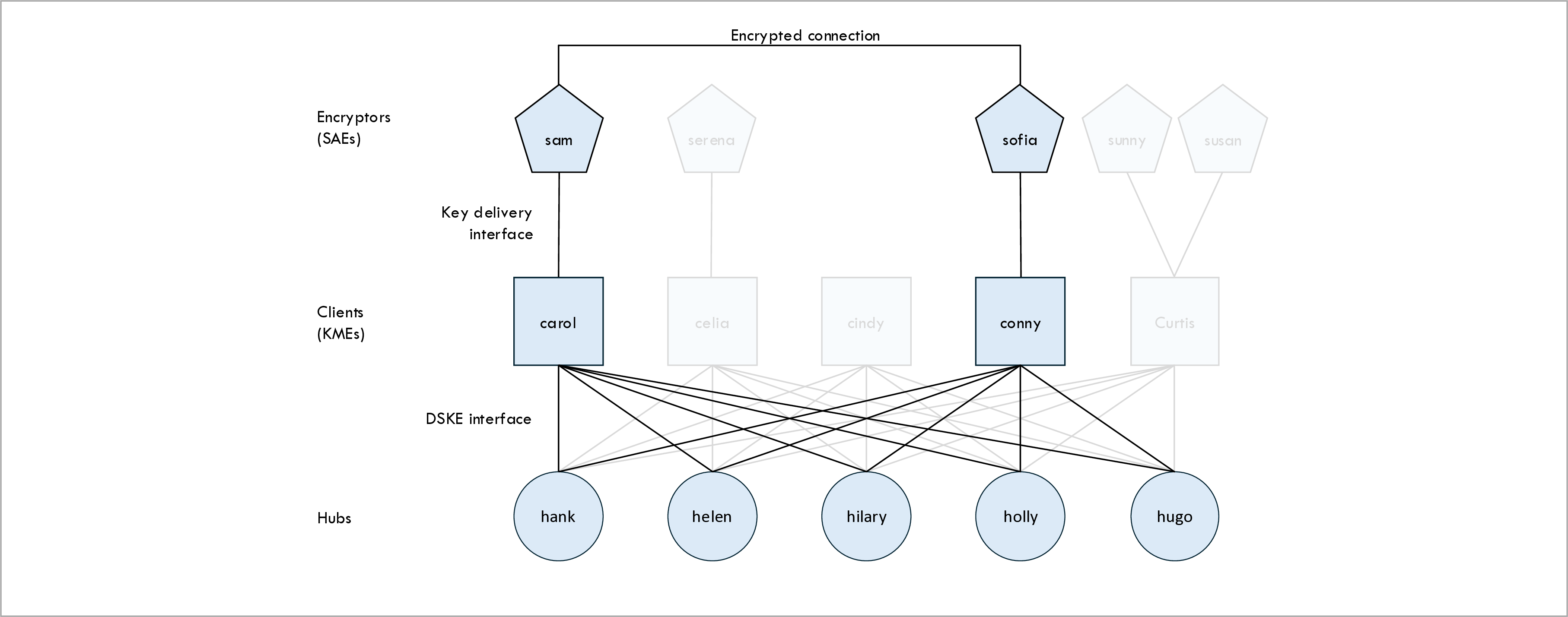
The topology consists of the following types of nodes:
-
Clients, also known as DSKE Clients or Key Management Enitities (KMEs).
-
Hubs, also known as DSKE Security Hubs.
-
Encryptors, also known as Secure Application Entities (SAEs).
Clients
The DSKE client nodes, or just clients for short, are represented by blue squares in the topology diagram above. Standard IETF ETSI QKD 014 uses the term Key Management Entity (KME) instead of client.
There are five clients in our example: Carol, Celia, Cindy, Conny, and Curtis.
The clients are responsible for:
-
Registering themselves with hubs.
-
Requesting Pre-Shared Random Data (PSRD) from hubs when needed.
-
Establishing keys and delivering those keys to encryptors upon request.
-
Splitting keys into key shares and relaying those keys shares from client to client through a set of hubs.
Below, we describe the concepts of PSRD and key shares and each of these steps in more detail.
In the example scenario, clients Carol and Conny are responsible for producing an encryption key and for delivering this key to encryptors Sam and Sofia respectively. The other clients are faded out because they play no role in our example.
In our implementation, each client runs in a separate process, listening on a separate HTTP port.
Hubs
The the DSKE hub nodes, or just hubs for short, are represented by blue circles in the topology diagram above. IETF draft draft-mwag-dske-02 uses the term security hub.
There are five hubs in our example: Hank, Helen, Hilary, Holly, and Hugo.
In our example, the number of clients happens to be equal to the number of hubs. This is a coincidence; typically there are more clients than hubs.
The hubs are responsible for:
-
Allowing clients to register themselves with the hubs.
-
Distributing Pre-Shared Random Data (PSRD) to clients upon request.
-
Relaying key shares from client to client.
Once again, we describe these steps in more detail below.
In the example scenario, all five hubs are involved in relaying the key shares between clients Carol and Conny to produce a key between encryptors Sam and Sofia.
In our implementation, each hub also runs in a separate process, listening on a separate HTTP port.
Encryptors
The encryptors are the devices that consume the keys that are produced by the clients and use them to encrypt user traffic that is sent through a encrypted connection. IETF ETSI QKD 014 uses the term Secure Application Entity (SAE) instead of encryptor.
Examples of encryptors include:
- Optical encryptors, such as Ciena WaveLogic.
- MACsec encryptors, such as Juniper QFX switches.
- IPsec encryptors, such as FortiNet FortiGate Next-Generation Firewalls.
- TLS / SSL encryptors, such as F5 NGINX.
There are five encryptors in our example topology: Sam, Serena, Sofia, Sunny and Susan.
Each encryptor is connected to one client and each client can have zero or more encryptors connected to it. In the example, client Carol has one encryptor (Sam), client Celia has one encryptor (Serena), client Cindy has zero encryptors, client Connie has one encryptor (Sofia), and client Curtis has two encryptors (Sunny and Susan).
The example scenarios use encryptors Sam and Sofia; the other encryptors are faded out.
The encryptors are responsible for:
-
Requesting an encryption key from the clients (they may periodically request a fresh key for key roll-overs).
-
Use that encryption key to encrypt the user data that is sent over the encrypted connection.
In our implementation, the manager.py script takes on the role of the encryptors, invoking the
ETSI QKD 014 interface to request keys from the clients.
Local distributors
The IETF draft has more more type of node: local distributors. We have not implemented local distributors; hubs deliver PSRD directly to clients without local distributors in between.
Connectivity
The topology diagram above contains lines that represent the connectivity between the various network nodes (clients, hubs, encryptors). These lines are not intended to represent single-hop point-to-point physical connections. Instead they represent potentially multi-hop IP connectivity between the network nodes; each link may contain multiple switch or router hops.
DSKE vs ETSI terminology
The DSKE IETF draft and arXiv papers use different terminology than the European Telecommunications Standardization Institute (ETSI). The following table shows how the different terminologies map to each other:
| DSKE term | ETSI term |
|---|---|
| Client DSKE Client |
Key Management Entity (KME) |
| Client name | KME ID |
| Hub Security Hub DSKE Security Hub |
Trusted Relay Node (TRN) [1] |
| Encryptor | Secure Application Entity (SAE) |
| Encryptor name | SAE ID |
[1] An ETSI Trusted Relay Node (TRN) is only very roughly equivalent to DSKE Security Hub; for example ETSI does not have the concept of splitting a key into shares or Pre-Shared Random Data (PSRD).
High-level overview
We start with a high-level overview of how the protocol works. Our goal is try to avoid losing the forest for the trees later on when we dive into the details. We gloss over many important details which will be explained later.
We have a network consisting of network nodes. These nodes are connected to each other using a normal IP network (i.e. using routers and switches).
Some of these nodes want to exchange encrypted traffic with each other, and for this reason they need to agree on encryption keys. We refer to these nodes as encryptors.
Each encryptor is connected to a DSKE client, or client for short. The clients are responsible for producing the symmetric encryption keys and for delivering those encryption keys to the encryptors.
The clients run the DSKE protocol as the key establishment protocol.
The DSKE protocol relies heavily on using very large blocks of Pre-Shared Random Data (PSRD).
Before a pair of clients can establish keys, they first need to exchange blocks of PSRD.
The exchange of PSRD uses what we refer to as a secure out-of-band mechanism. Think, for example, of using armed guards to exchange tamper-proof disks full of random data, where the disks are destroyed after the same block of PSRD is delivered to each of a pair of nodes.
Later, we will see that clients don’t exchange PSRD directly with each other, but through a set of intermediate nodes called DSKE Security Hubs, or just hubs for short.
Imagine, for now, that two clients Carol and Celia have exchanged blocks of PSRD. This means that Carol and Celia both have a identical copies of the PSRD blocks, and no-one else knows what these blocks of PSRD are.
Carol and Celia can now agree on a Carol-Celia encryption key using a public conversation. For example, Carol could announce that she will use bytes numbers 100 through 228 of PSRD block number 123 as the key. We refer to this as the meta-data for the encryption key. Since Celia has a copy of PSRD block 123, she can extract bytes 100 through 228 and find the same encryption key. But no-one else knows the contents of PSRD block 123, so no-one else can determine what the Carol-Celia encryption key is.
Carol and Celia need to make sure that they are really talking to each other and not to some imposter. In other words, Carol and Celia need to authenticate each other. The clients authenticate messages by extracting an authentication key from the PSRD. The sender (say Carol) allocates the authentication key and uses it to sign the message. Carol sends the meta-data for the authentication key (but not the key value), the signature, and the message itself to the receiver (say Celia). Celia uses the received key meta-data to extract the authentication key value from her copy of the PSRD and uses it to validate the received signature.
Once Carol and Celia have established an encryption key, they deliver that encryption key to the encryptors using a key delivery protocol such as ETSI QKD 014 or SKIP.
The scheme that we have described thus far becomes impractical if we have a very large number of clients. Each client would have to pro-actively and a-priori exchange PSRD with each of the other clients on the network that it could potentially wish to communicate with at some point in the future.
For this reason, we introduce a second type of node that we refer to as a DSKE security hub, or simply hub for short.
Instead of establishing a key directly between a pair of clients, we use the hubs as a sort of Trusted Relay Nodes (TRNs). The clients do not establish PSRD with directly with each other; instead, the clients establish PSRD with the hubs.
As an example, let’s say we have two clients Carol and Celia, and one hub Hank. And let’s say Carol and Celia want to agree on a key. First, Carol and Hank agree on a local Carol-Hank key using the mechanism described above. Then, Celia and Hank agree on a local Celia-Hank key, also using the mechanism described above. Finally, the end-to-end Carol-Celia key is established. Carol allocates some random bytes as the end-to-end Carol-Celia key. Carol sends the end-to-end Carol-Celia key to Hank, encrypting it using the local Carol-Hank key. And then Hank forwards the end-to-end Carol-Celia key to Celia, encrypting it using the local Celia-Hank key.
Note that the end-to-end Carol-Celia key is decrypted and re-encrypted at Hank in this process. In other words, for a brief moment, Hank knows what the end-to-end Carol-Celia key is. We have to trust Hank not to abuse that knowledge or be hacked by an attacker to steal that knowledge. Because Hank needs to be trusted, Hank is called a Trusted Relay Node (TRN).
Also, hub Hank becomes a Single Point of Failure (SPoF). If hub Hank fails, the clients relying on Hank are enable to establish keys.
To ameliorate both the problem of having to trust the hub node and the problem of the hub node being a single point of failure, we introduce the concept of using multiple hub nodes in parallel. This is where the “Distributed” in “Distributed Symmetric Key Establishment” comes from.
To understand how using multiple hubs works, we fist need to understand Shamir’s Secret Sharing (SSS) algorithm.
Shamir’s secret sharing allows us to split the end-to-end Carol-Celia key into some number (n) of parts. Here, n is the number of hubs that we will use in parallel to relay the key. Each part is called a share of the key. The original key can be reconstructed if you have at least k out of the original n shares (were k is some number smaller than n). If you have fewer than k shares, no information about the secret can be extracted.
We use Shamir’s secret sharing as follows. After Carol allocates the end-to-end Carol-Celia key, she splits the key up into n shares. She then relays each of these n shares to Celia using a different hub. Thus, she uses n hubs in parallel to relay each of the n shares.
This solves both the trusting problem and the single point of failure problem.
Each hub only has knowledge of a single share of the end-to-end key. It would require k hubs to conspire with each other (or k hubs to be hacked) for the hubs or the attacker to reconstruct the end-to-end key. As long as fewer than k shares are leaked, no information whatsoever about the end-to-end key is leaker.
Also, if some of the hubs fail, the end-to-end key establishment can still complete successfully. The protocol continues to work as long as at least k hubs remain (i.e. as longs as no more than n - k nodes fail).
Interfaces
The topology contains the following software interfaces:
- DSKE interface (in-band and out-of-band).
- Key delivery interface.
- Management interface.
DSKE interface
The DSKE interface is the interface between the clients and the hubs. The clients and hubs run the DSKE protocol over this interface. Using the DSKE protocol, the clients and the hubs collaborate with each other to establish the keys.
Key delivery interface
The key delivery interface is the interface between the clients and the encryptors. The encryptors use the key delivery interface to retrieve keys from the clients.
There are two standard key delivery protocols:
-
ETSI QKD 014 is standardized by ETSI. This protocol is supported by multiple encryptor devices from different vendors.
-
The Secure Key Integration Protocol (SKIP) is defined in IETF draft IETF draft draft-cisco-skip. This protocol is supported by some Cisco encryptors.
The code in this repository uses a simplified implementation of ETSI QKD 014. The point of this repository is not to have a full-blown implementation of ETSI QKD 014 but rather to implement the DSKE protocol. See QuKayDee or qkd_kme_server if you want to get experience with the ETSI QKD 014 protocol.
Management interface
This repository contains a management script (manager.py) that is used to control the network
nodes.
It can start nodes, stop nodes, report the status of nodes, and request keys.
See the
getting started guide
or the
user guide
for more information.
The clients and the hubs expose a management interface, which is a REST API, to interact with the
management script.
Shamir’s Secret Sharing (SSS)
Before we describe the DSKE protocol, we first describe Shamir’s Secret Sharing (SSS) algorithm, which is an essential component in the DSKE protocol.
Shamir’s Secret Sharing allows a secret to be split up into some number (n) of parts. Each part is called a share of the secret. The original secret can be reconstructed if you have at least k out of the original n shares (were k is some number smaller than n). If you have fewer than k shares, no information about the secret can be extracted.
In the DSKE protocol, the key that is established for the encryptors is the secret. The key is split up into n key shares, where n is the number of hubs. Each key share is relayed from the initiator client to the responder client through a different hub.
As a result of this arrangement:
- An attacker needs to compromise at least k hubs to recover the key.
- The protocol is resilient against failures or denial-of-service attacks as long as at least k hubs survive.
Out-of-band versus in-band
Certain steps of the DSKE protocol, as described in the IETF draft, are not part of the DSKE protocol per-se. Instead, these steps are implemented using some secure mechanism that is outside of the scope of the DSKE protocol itself. We refer to these steps as out-of-band steps; in ladder diagrams they are shown in red. We refer to the steps that are actually part of the DSKE protocol itself as in-band steps; in ladder diagrams they are shown in green.
The out-of-band steps include:
- Clients registering themselves with hubs.
- Hubs delivering Pre-Shared Random Data (PSRD) to clients.
The IETF draft gives some examples of how the out-of-band steps could be implemented in real life, including physical delivery using Hardware Security Modules (HSMs), encrypted USBs, military key transfer devices , SIM cards, NFC, QKD, etc.
In our code we implement the out-of-band DSKE interface as an HTTP REST interface. In real life HTTP would not be used for this purpose; instead some secure physical delivery mechanism would be used, as we just mentioned. We use HTTP as a simulation of this physical mechanism to enable automated testing of use case scenarios.
Our code also implements the in-band DSKE interface as an HTTP REST interface. This REST interface runs over normal HTTP and not over HTTPS. The DSKE protocol uses its own authentication and encryption mechanisms which are described below.
Pre-Shared Random Data (PSRD)
The concept of Pre-Shared Random Data (PSRD) plays a central role in the DSKE protocol.
Each client and each hub use some secure out-of-band mechanism to agree on large blocks of random data, which we refer to as PSRD blocks. The data is completely random and meaningless and should be generated by a high-quality entropy source, for example a Quantum Random Number Generator (QRNG). These blocks of PSRD can be very large, e.g. many gigabytes.
The random data in the PSRD blocks is consumed by the clients and by the hubs for the purpose of authenticating DSKE protocol messages and for encrypting specific fields (namely the key shares) in DSKE protocol messages.
Each byte of PSRD is used once and once only. The PSRD is essentially used for One Time Pad (OTP) encryption, which contributes to the Information Theoretic Security (ITS) of the protocol.
When the clients or the hubs run low on PSRD, there is an out-of-band mechanism for the clients to request additional blocks of PSRD from the hubs.
In the code, each block of PSRD is represented by a Block object.
Each block is uniquely identified by a Universally Unique Identifier (UUID).
The clients and the hubs may have exchanged multiple PSRD blocks.
The pool of available PSRD blocks is represented by a Pool object.
When a client or a hub needs to authenticate or encrypt a DSKE message, it allocates
some bytes from the pool.
In the code, such an allocation is represented by an Allocation object.
An allocation may consist of multiple fragments from different blocks.
This happens when an allocation requests more bytes than are remaining in a block.
These fragments are represented in the code by Fragment objects.
One of the fundamental ideas in the DSKE protocol is that a given client and a given hub can agree on a shared secret by exchanging the meta-data (and only the meta-data, not the data itself) for an allocation.
As a simplified example, the client and the hub might agree to use an allocation that consists of bytes 100 to 200 of PSRD block 11111111-2222-3333-4444-555555555555. Given the range of bytes and the block UUID, both the client and the hub are able to retrieve the shared secret data from their pool. But any attacker cannot retrieve the shared secret data because the data itself is never on the wire (only the meta-data) and the attacker does not have access to the PSRD.
For more details about the implementation see the developer guide.
Key relaying
The following two figures show how the DSKE protocol establishes a key between two clients Carol and Conny.
Before they establish a key, client Carol and Conny have already obtained blocks of PSRD from each hub using the DSKE out-of-band protocol (these are the red lines in the figures).
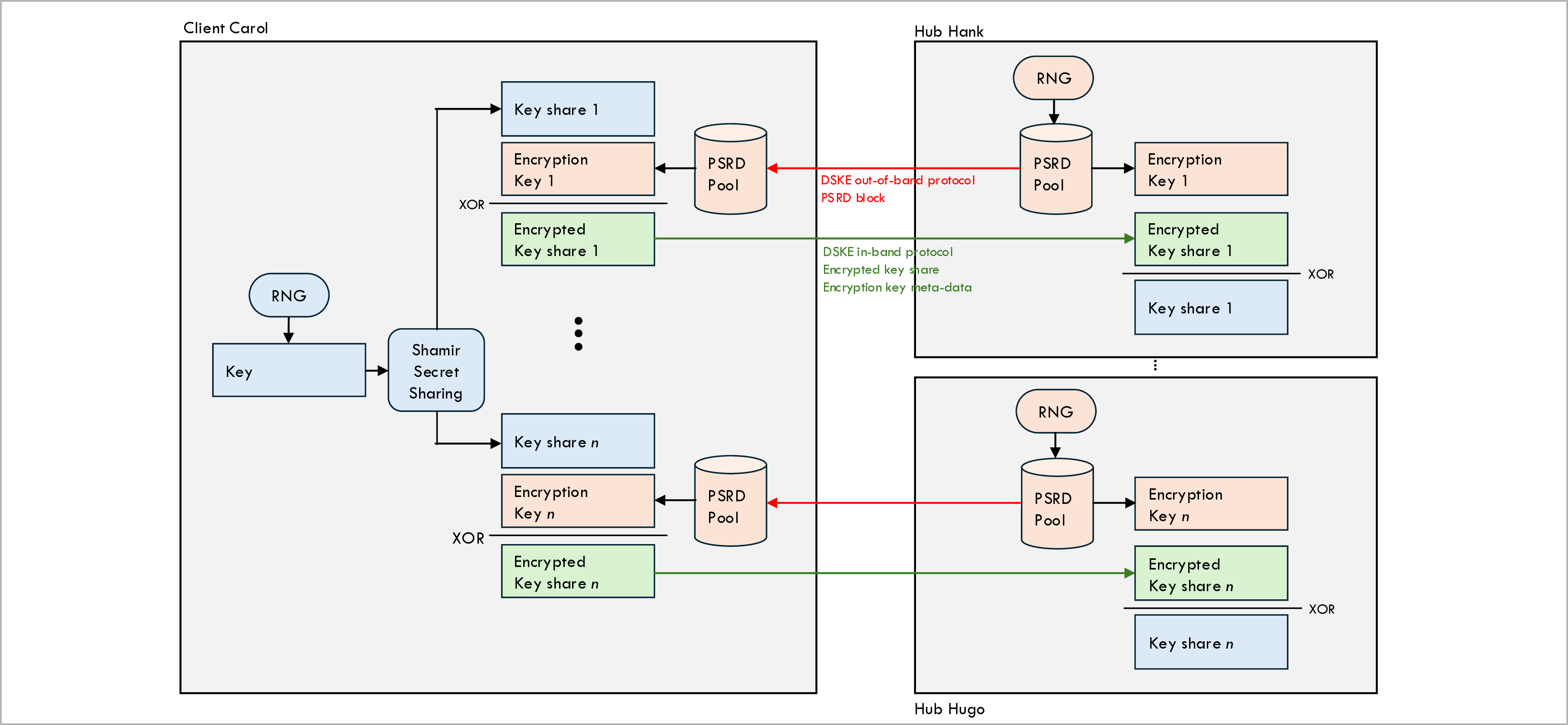
The figure above shows the first half of the relaying process, namely relaying key shares from a client Carol to all hubs.
-
Client Carol uses a Random Number Generator (RNG) to generate the key that she wishes to share with client Conny.
-
Client Carol uses Shamir’s Secret Sharing (SSS) algorithm to split the key into n key shares (or just shares for short), where n is the number of hubs that is going to be used to relay the key.
-
Client Carol is going to send each share to a different hub, so that the hub can relay the share to the remote client Conny (second figure).
-
However, before client Carols sends a share to a particular hub, she first encrypts the share using an encryption key that is allocated from the PSRD pool associated with that particular hub.
-
When client Carol sends the encrypted key share to a hub, she includes the meta-data about the encryption key to the hub. This allows the hub to retrieve the exact same decryption key from its local copy of the PSRD pool. The encryption key value itself is never on-the-wire; only it’s public metadata.
Note that the blue keys are different keys than the red keys in the figures. The blue keys are the user keys that will be delivered to the encryptors. These are split into key shares for relaying across the hubs. The red keys are key share encryption keys. These are allocated from the PSRD pools.
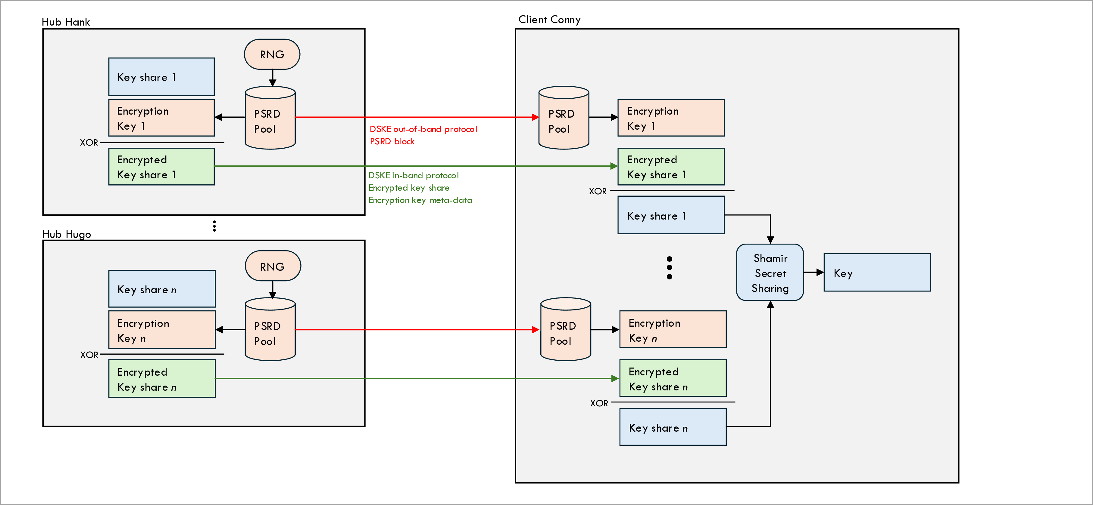
The figure above shows the second half of the relaying process, namely relaying key shares from all hubs to client Conny.
-
Client Conny receives and encrypted key share from each hob (to be more precise: from at least k out of the n hubs).
-
Along with the encrypted key share, the DSKE protocol message also contains meta-data about the encryption key that the hub used to encrypt the key share.
-
Client Conny uses this meta-data to allocate the description key from the PSRD pool associated with that particular hub and decrypt the encrypted message share.
-
Client Conny uses Shamir’s Secret Sharing algorithm to reconstruct Carol’s key from the decrypted key shares.
Trusted Relay Nodes (TRNs)
In Quantum Key Distribution (QKD) there is the concept of Trusted Relay Nodes (TRNs). Each QKD link has a maximum distance, and when you need to generate a QKD key across a greater distance a trusted relay node can be used to relay the key.
The following figure shows how a trusted relay node works: the trusted relay node uses the red B-C key to encrypt the green A-B node and relay it to node C. After the relay is completed, the green A-B key becomes the end-to-end A-C key.
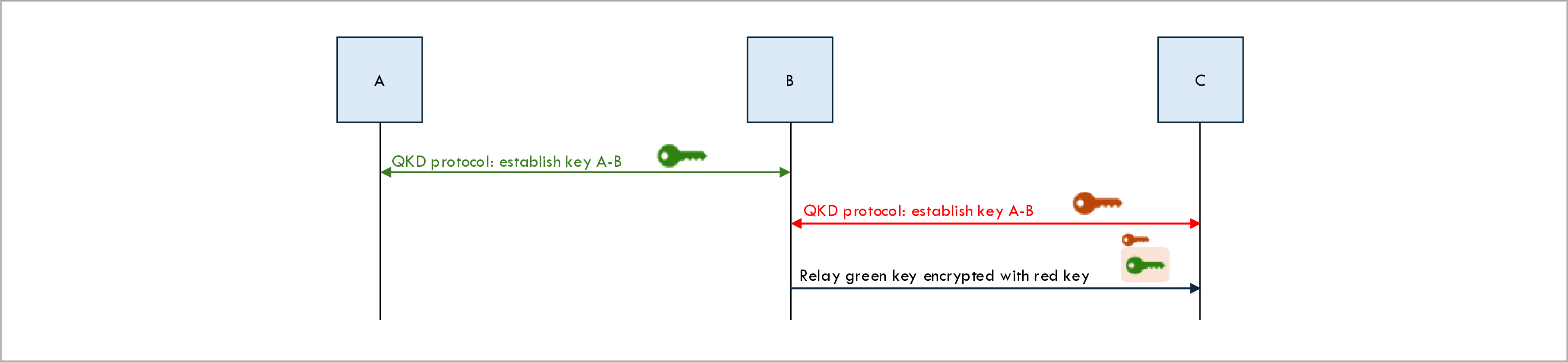
The problem with this approach is that the final A-C key (the green key) is not only known by the end-points A and C but also by the relay node B. You have to trust that relay node B will not abuse or leak knowledge of the end-to-end key. This is why B is called a trusted relay node.
In Distribute Symmetric Key Encryption (DSKE) the problem of having to trust relay nodes is addressed using Shamir’s Secret Sharing (SSS). The secret key is split into n key shares. Each hub (which is a relay node) only knows one share of the key. At least k hubs would have to conspire with each other to be able to gain any knowledge of the complete key.
Similarly, attacker Eve would have to hack at least k hub nodes and recover k shares to be
recover the secret user key.
Note that only applies to hub nodes and not to links;
even if attacker Eve hacks all n client-to-hub links and taps all POST key-share and
all GET key-share messages, she is still not able to recover the secret user key
because the key shares in the messages are One-Time-Pad (OTP) encrypted using encryption
keys allocated from Pre-Shared Random Data (PSRD).
This same mechanism also provides resilience to the DSKE protocol: as long as there are k surviving hub nodes, the DSKE protocol continues to work in the face of hub failures (i.e. n - k hubs can fail).
Message authentication
To protect against Man-in-the-middle attacks all in-band DSKE protocol message must be authenticated.
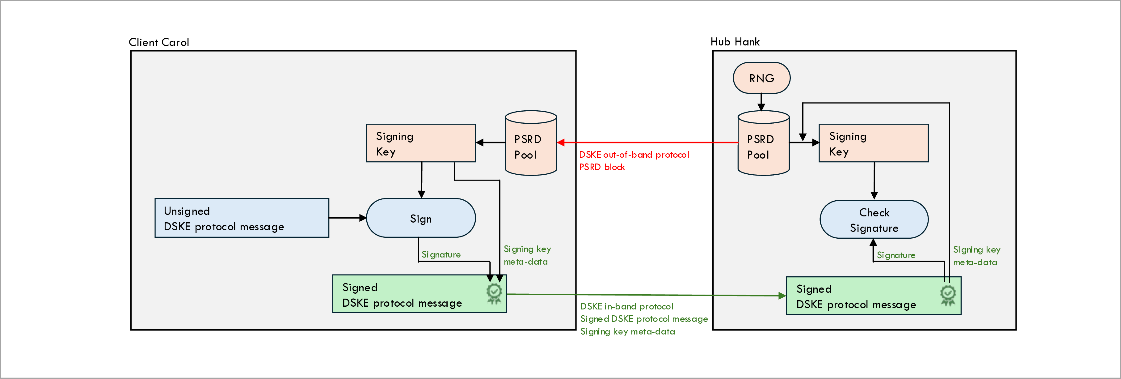
The above figure shows how messages sent from clients to hubs are authenticated (messages sent from hubs to clients are authenticated in a similar way).
Client Carol signs sent messages as follows:
-
Client Carol wants to authenticate an in-band DSKE protocol message for hub Hank. This in-band DSKE message is an HTTP REST message that may contain query parameters and/or a message body.
-
Client Carol allocates a signing key from the PSRD pool associated with hub Hank.
-
Client Carol computes the signature for the message in the form of a Hashed Message Authentication Code (HMAC) using the message to be signed and the allocated signing key as inputs. The HMAC signature is computed over the query parameters and the body of the signed message.
-
Carol computes the signature for the request by computing the SHA256 Hashed Message Authentication Code (HMAC) over the concatenation of (a) the content of the request (b) the query parameters of the request and (c) the signing key allocated in step 1.
-
Carol encodes the meta-data of the signing key (but not the signing key value itself) plus the computed signature into a string and puts this string in the
DSKE-Signatureheader. The encoding format is detailed below.
Hub Hank validates the signature on received messages as follows:
-
Hub Hank extracts the following two piece of information from the
DSKE-Signatureheader on the received message: (a) the meta-data for the signing key and (b) the HMAC signature. -
Hub Hank retrieves the signing key from the remote PSRD pool associated with client Carol using the signing key meta-data extracted from the
DSKE-Signatureheader. -
Hub Hank performs its own local computation of the signature by computing the HMAC over the message received from Client Carol and the singing key retrieved from its local PSRD pool.
-
If the locally computed signature matches the received signature, the authentication succeeds.
Note that we don’t authenticate out-of-band DSKE messages because the out-of-band REST messages are only intended to simulated what would be a secure physical mechanism in real for automated testing purposes.
The response to a DSKE request is usually also signed in the same way, using a different signing key freshly allocated from the local PSRD pool of the receiver. All success responses and most error responses are signed. In some errors (e.g. the node is out of PSRD data) the response cannot be signed and the error response is sent without a signature.
The DSKE-Signature header is encoded as follows:
-
The meta-data of the singing key, followed by a semi-colon (;), followed by the signature encoded using base64 encoding.
-
The meta-data of the signing key is encoded as one or more encoded fragment meta-data strings, separated by commas.
-
Each fragment meta-data string is encoded as the block UUID, the start byte within the block, and the size of the fragment, separated by colons.
-
Note that the key data (fragment data) is not encoded into the meta-data.
Example of an encoded signature:
9ad7f620-5a0c-4979-8a2d-66142e06fd79:0:20,cda527e9-5ca7-40d6-a842-0b606597611c:0:12;V12fwNZiooqE1x0beAdQ4fo2YXnOCTPbUgqG38eUQc4=
The part after the semi-colon is the base64-encoded signature:
V12fwNZiooqE1x0beAdQ4fo2YXnOCTPbUgqG38eUQc4=
The part before the semi-colon is the sequence of two fragments:
9ad7f620-5a0c-4979-8a2d-66142e06fd79:0:20,cda527e9-5ca7-40d6-a842-0b606597611c:0:12
The first fragment is bytes 0 through 19 of block 9ad7f620-5a0c-4979-8a2d-66142e06fd79:
9ad7f620-5a0c-4979-8a2d-66142e06fd79:0:20
And the second fragment is bytes 0 through 11 of block cda527e9-5ca7-40d6-a842-0b606597611c:
cda527e9-5ca7-40d6-a842-0b606597611c:0:12
Pool ownership
So far, we have seen several scenarios where a node (i.e. a client or a hub) allocates a key from a local PSRD pool and uses that key to encrypt a key share or to sign a DSKE message. The node then sends meta-data about the allocated key to a peer node. This allows the peer node to use the received key meta-data to retrieve the same key from its local PSRD pool and use that key to decrypt the key share or to validate the signature.
Sometimes the node who allocates the key and sends the meta-data is a client and other times it is a hub. This leads to a race condition: when two nodes (a client and hub) send a message to each other at roughly the same time, it may happen that they allocate the same bytes from the PSRD pool. When they receive the meta-data from their peer, they find that the bytes indicated in the received meta-data are already allocated for a different purpose.
We solve this problem by having each node keep two separate PSRD pools: one pool from which the client allocates bytes and a different pool from which the hub allocates bytes. We refer to this as the concept of pool ownership: each PSRD pool is owned by either the client or the hub.
Client onboarding
Now that we have explained the basic concepts behind the DSKE protocol, we are finally ready to describe the actual protocol in detail. We start with client onboarding.
The following ladder diagram shows the onboarding of a new client in the network. Note that all the steps in the ladder diagram are red, which means that they are all out-of-band steps.
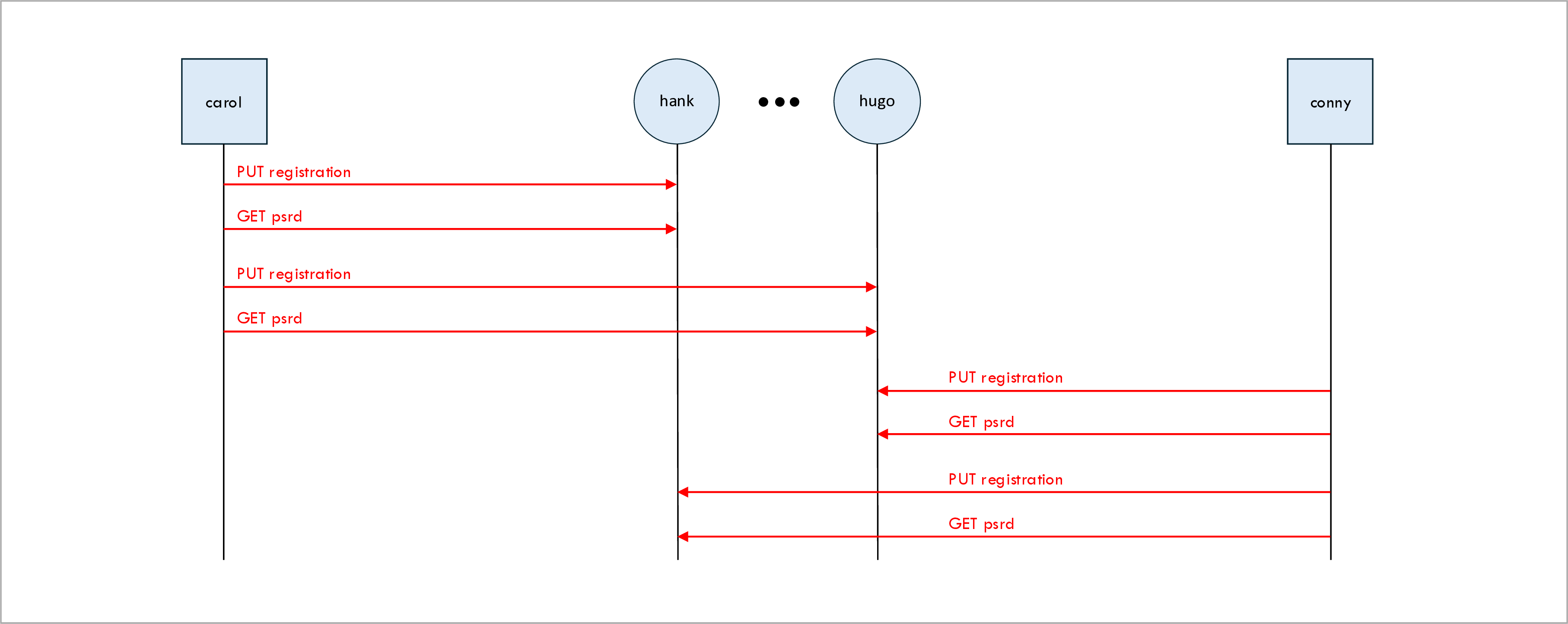
The steps for onboarding a new client into the network are as follows:
-
The client registers itself with each hub.
-
The client requests its initial block of Pre-Shared Random Data (PSRD) from each hub.
Client registration
The first thing a client does after it starts up is to register itself with each hub. In the above example, both client Carol and client Conny register themselves with each of the five hubs Hank, Helen, Hilary, Holly, and Hugo.
The client knows which hubs to register itself with because the list of hub URLs is provided to the client process as a command-line argument when it starts up. In the current implementation, the hub is not provided with a lists of clients; it simply allows any client to register itself.
If the hub is not yet running, the registration will fail. In that case, the client periodically keeps retrying the registration.
The client registration is an HTTP PUT message. As a result, the client registration is idem-potent and it is not an error for a client to register itself multiple times. This can happen, for example, when a client crashes and restarts.
In the request, the client provides its own client_name.
The client also provides a list of encryptor_names that are attached to the client.
This is used by the hub to verify whether the client only produces or consumes keys for directly
attached encryptors.
In the response, the hub provides its hub_name.
Method: PUT
URL: /hub/{hub_name}/dske/oob/v1/registration
Note that we include the node name (in this case hub_name) in the path of the URL;
this allows deployments where all nodes run on a single server on a single port
behind a reverse proxy (e.g.
NGINX
)
where the reverse proxy uses the node name in the URL to dispatch the request to the correct
process.
Request body:
{
  "client_name": "string"   # The name of the client.
  "encryptor_names": [      # List of encryptors attached to the client
    "string", ...           # Name of one encryptor attached to the client
  ]
}
Successful response body:
{
  "hub_name": "string"   # The name of the hub.
}
Request Pre-Shared Random Data (PSRD)
Once a client has successfully registered itself with a particular hub, it requests its initial blocks of Pre-Shared Random Data (PSRD) from that hub. It requests one initial client-owned PSRD block and it requests one initial hub-owned PSRD block (see discussion of PSRD block ownership above).
Each node consumes data from the PSRD blocks for key-share encryption and for message authentication. When a PSRD block nears the point of being fully consumed, the client will request a new PSRD block to replenish the pool of PSRD data.
Method: GET
URL: /hub/{hub_name}/dske/oob/v1/psrd
Query parameters:
| Name | Type | Description |
|---|---|---|
client_name |
string | The client name. |
owner |
string | The owner of the PSRD block: client or hub. See discussion of PSRD block ownership above. |
size |
integer | The size in bytes of the requested PSRD block. |
Request body: None
Successful response body:
{
  "block_uuid": "string",   # A UUID chosen by the hub to uniquely identify the PSRD block.
  "data": "string"          # The random bytes in the PSRD block, as a base64 encoded string.
}
Key establishment
The following ladder diagram shows the establishment of a new key:
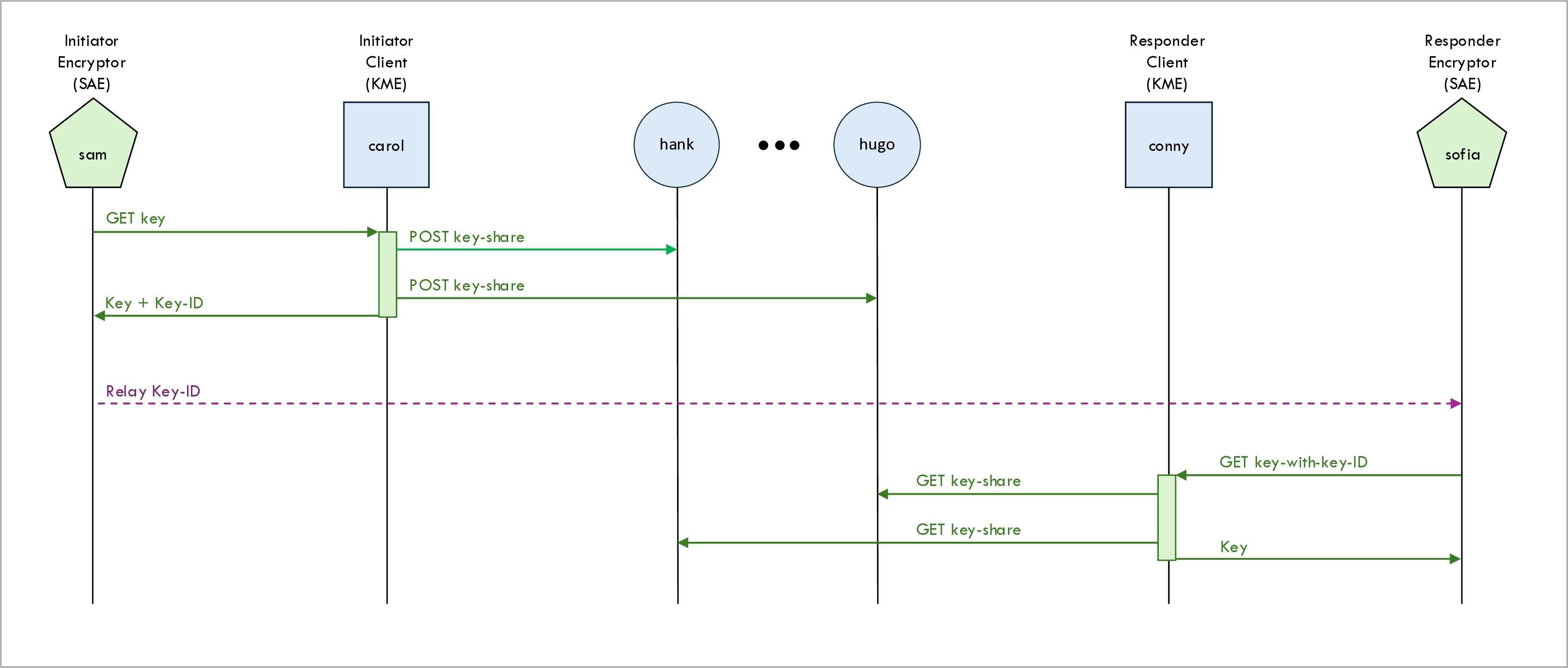
Initiator and responder roles
In the example scenario shown in the above ladder diagram, encryptors Sam and Sofia establish a key.
In each key establishment one of the two encryptors (Sam in this example) is the initiator: he initiates the key establishment process. The other encryptor encryptor (Sofia) is the responder: she follows the lead of the initiator.
ETSI GS QKD 014 V1.1.1 (2019-02) still uses the terms master Secure Application Entity (SAE) and slave SAE.
These terms master and slave will be updated to initiator and responder in version v2 of the
API which is expected to be published soon.
Initiator encryptor gets key
The initiator encryptor (Sam) the initiates the key establishment process by invoking the
Get key API as defined in section 5.3 of
ETSI GS QKD 014 V1.1.1 (2019-02).
The client-side of this API call is implemented in the manager script manager.py and the
server-side is implemented by the client node.
(The naming is confusing here - the client node is called that because it is the client-side of
the client-hub interface.)
We only implement a minimal subset of the ETSI QKD 014 interface - the point of this repository is to demonstrate a DSKE protocol, not to have a fully compliant ETSI QKD 014 implementation. See QuKayDee or qkd_kme_server if you want to experiment with a full ETSI QKD 014 implementation.
Method: GET
URL: /client/{client_name}/etsi/api/v1/keys/{slave_SAE_ID}/enc_keys
Note that this API call always referred to as the Get key API call, but the URL path
actually ends in enc_keys.
URL parameters:
| Name | Type | Description |
|---|---|---|
slave_SAE_ID |
string | The identifier of the slave Secure Application Entity (SAE), i.e. the responder encryptor. |
In this example, the slave SAE is encryptor Sofia.
Query parameters:
| Name | Type | Description |
|---|---|---|
size |
integer (optional) | The size in bits (not bytes) of the requested key. Must be a multiple of 8. |
The size parameter is optional; if it is not specified, the default key size is used.
(The ETSI QKD 014 Status API call can be used to find out what the default key size is.)
The ETSI QKD 014 specification also define one more query parameter number for the number
of requested keys, but this is not supported in our simplified implementation.
Request body: None
Headers:
| Name | Type | Description |
|---|---|---|
Authorization |
string | The SAE ID (the encryptor name) of the master SAE |
Note that the identity of the master SAE (i.e. the SAE ID of the encryptor invoking the Get Key API) is not included anywhere GET request URL, query parameters, or request content. In a real fully compliant implementation of the ETSI QKD 014 interface, we would use HTTPS instead of HTTP and the identity of the invoking SAE would be implicitly derived from the authentication mechanisms (i.e. from the certificates included in the TLS handshake).
In our simplified implementation, we run over HTTP instead of HTTPS.
We cannot use TLS authentication or certificates to determine the identity of the invoking SAE.
For that reason, we use the Authorization header to contain the SAE ID of the invoking SAE.
This follows the spirit of the ETSI QKD 014 specification if not the letter.
Successful response body:
{
  "keys": {
    "key_ID": "string",   # A UUID uniquely identifying the key
    "key": "string"       # The base64 encoded key value
  }
}
Initiator client posts key shares to all hubs
When an initiator client (KME) receives a Get key request from an initiator encryptor (SAE),
the client performs the following steps to produce the key and to deliver it back to the encryptor:
-
Randomly generate a key value.
-
Use Shamir’s Secret Sharing (SSS) algorithm to split the key into n shares, where n is the number of hubs over which the key will be relayed.
-
Relays each of the n shares to a different hub using the
POST key-shareAPI call. -
The share value in the
POST key-shareAPI call is encrypted using the process described above: the client allocates a number of bytes equal to the user key size from the PSRD pool and uses it as a one-time pad to encrypt the share. The client includes the meta-data of the PSRD pool allocation in thePOST key-shareAPI call; this allows the hub to allocate the same bytes from its PSRD pool and decrypt the share value. -
The whole
POST key-sharemessage is also authenticated as described above: the client allocates a number of bytes equal to the authentication key size from the PSRD pool and uses to compute an HMAC to sign the message. Both the signature itself and also the meta-data of the PSRD pool allocation are encoded into theDSKE-SignatureHTTP header. When the hub receives thePOST key-sharemessage, he uses the meta-data to allocate the same authentication key from his local PSRD pool and uses it to verify the signature. -
When at least k shares have been successfully relayed to hubs, the client returns the key ID (a UUID) and the key value to the encryptor.
Method: POST
URL: /hub/{hub_name}/dske/api/v1/key-share
Request body:
{
  "master_client_name": "string",     # The name of the master client.
  "master_sae_id": "string",          # The SAE ID (encryptor name) of the master SAE
  "slave_sae_id": "string",           # The SAE ID (encryptor name) of the slave SAE
  "user_key_id": "string",            # The UUID of the user key.
  "share_index": "integer",           # The index of the share (0, 1, ..., n-1).
  "encryption_key_allocation": {      # The PSRD pool allocation for the share encryption key.
    "fragments": [                    # List of fragments in the allocation
      {                               # One fragment in the allocation
        block_uuid: "string",         # The UUID of the PSRD block from which the fragment was allocated.
        start_byte: "integer",        # The index of the start byte for the fragment within the block.
        size: "integer"               # The size of the fragment
      }, ...
    ]
  },
  "encrypted_share_value": "string"   # Base64 encoded encrypted share value
}
Headers:
| Name | Type | Description |
|---|---|---|
DSKE-Signature |
string | The authentication signature of the request. |
See section message authentication.
Successful response body: None
Initiator encryptor sends key ID to responder encryptor
Once the initiator encryptor (Sam) has received the key ID and the key value from the initiator client (Carol), the initiator encryptor (Sam) uses some mechanism to send the key ID (but not the key value) to the responder encryptor (Sofia). Note that (unlike the key value) the key ID is not a secret; it is perfectly okay to send it over a public channel.
The exact mechanism that is used for sending the key ID depends on which encryption protocol the encryptors Sam and Sofia as using. For example, if they are running IPsec as the encryption protocol, the IPsec protocol uses some extensions defined in RFC8784: Mixing Preshared Keys in the Internet Key Exchange Protocol Version 2 (IKEv2) for Post-quantum Security. The details are too complex to describe here; see this blog post or this webinar for more information. Other encryption protocols (e.g. TLS, MACsec, optical encryption) have similar but different mechanisms.
In our code the transfer of the key ID from initiator to responder encryptor is implemented in
the manager.py script.
Responder encryptor gets key
Once the responder encryptor (Sofia) has received the key ID from the initiator encryptor
(Sam), he retrieves the key value from the responder client (Conny) by invoking the
Get key with key IDs API as defined in section 5.4 of
ETSI GS QKD 014 V1.1.1 (2019-02).
Method: GET
URL: /client/{client_name}/etsi/api/v1/keys/{master_SAE_ID}/dec_keys
Note that this API call always referred to as the Get key with key IDs API call, but the URL path
actually ends in dec_keys.
URL parameters:
| Name | Type | Description |
|---|---|---|
master_SAE_ID |
string | The identifier of the master Secure Application Entity (SAE), i.e. the initiator encryptor. |
As in the Get Key flow
above
the current simplified implementation requires that SAE IDs are the same as the KME IDs (client
names) to which they are attached.
Query parameters:
| Name | Type | Description |
|---|---|---|
key_ID |
UUID | The UUID of the requested key (as receive from the master SAE). |
Headers:
| Name | Type | Description |
|---|---|---|
Authorization |
string | The SAE ID (the encryptor name) of the master SAE |
See the Authorization header for the
Get Key API
for details.
Request body: None
Successful response body:
{
  "keys": {
    "key_ID": "string",   # The key UUID
    "key": "string"       # The base64 encoded key value
  }
}
Responder client gets key shares from all hubs
When a responder client (KME) receives a Get key with key IDs request from a responder
encryptor (SAE), the client performs the following steps to retrieve the key and to deliver it
back to the encryptor:
-
The client retrieves each of the n shares from a different hub using a
GET key-shareAPI call. -
Both the
GET key-sharerequest and response are authenticated using signing keys allocated from the PSRD pools. -
The share value returned in the
GET key-shareresponse is encrypted using an encryption key allocated from the PSRD pool. -
When the client has retrieved least k shares from the hubs, the user key is reconstructed from the shares using Shamir’s Secret Sharing (SSS) algorithm.
-
The reconstructed user key is returned to the encryptor in
Get key with key IDsresponse.
Method: GET
URL: /hub/{hub_name}/dske/api/v1/key-share
Query parameters:
| Name | Type | Description |
|---|---|---|
client_name |
string | The name of the client requesting the share. |
master_sae_id |
string | The SAE ID (encryptor name) of the master SAE for the key establishment. |
slave_sae_id |
string | The SAE ID (encryptor name) of the slave SAE for the key establishment. |
key_id |
UUID | The UUID of the user key whose share is being requested. |
Headers:
| Name | Type | Description |
|---|---|---|
DSKE-Signature |
string | The authentication signature of the request. |
See section message authentication.
Request body: None.
Successful response body:
{
  "share_index": "integer",           # The index of the share (0, 1, ..., n-1).
  "encryption_key_allocation": {      # The PSRD pool allocation for the share encryption key.
    "fragments": [                    # List of fragments in the allocation
      {                               # One fragment in the allocation
        block_uuid: "string",         # The UUID of the PSRD block from which the fragment was allocated.
        start_byte: "integer",        # The index of the start byte for the fragment within the block.
        size: "integer"               # The size of the fragment
      }, ...
    ]
  },
  "encrypted_share_value": "string"   # Base64 encoded encrypted share value
}
Comparison with other key establishment protocols
DSKE provides the same functionality, namely key establishment (also referred to as key agreement or key distribution) as some other protocols:
-
Traditional classical protocols such as Diffie-Hellman (DH) and Elliptic Curve Diffie-Hellman (ECDH).
-
Post-Quantum Cryptography (PQC) protocols such as the Module-Lattice Key Encapsulation Mechanism (ML-KEM).
-
Quantum Key Distribution (QKD) protocols such as Bennett and Brassard 84 (BB84).
The following table compares these protocols:
| Criterium | Traditional | PQC | QKD | DSKE |
|---|---|---|---|---|
| Needs special quantum hardware | No | No | Yes | No |
| Quantum safe | No | Yes | Yes | Yes |
| Based on hardness of mathematical problem | Yes (broken) | Yes (not broken) | No | No |
| Requires out-of-band distribution of information | No | No | No | Yes |
Differences between the IETF draft / arXiv papers and this implementation
In this section we describe the differences between the DSKE protocol as specified in draft-mwag-dske-02 and the DSKE protocol as implemented in this repository.
Share generation and authentication scheme
The arXiv paper contains a very detailed detailed and mathematical description of exact algorithm for generating the shares and for generating the authentication signature. The draft contains a shorter description. In both cases, we found the description complex and difficult to follow. We are not sure that our implementation matches the paper and the draft exactly. Once the project is more mature, we will attempt to contact the authors of the paper and draft to validate our implementation’s correctness.
REST message encoding
The IETF draft describes the DSKE protocol only at a high level of abstraction and does specify the message encoding. We had to choose some encoding of the messages ourselves. For educational reasons, we chose implement the protocol as a set of REST interfaces and use HTTP to encode the messages.
Since the draft doesn’t specify any particular encoding, using REST and HTTP is not a deviation from the draft per-se, but in a private email exchange one of the authors of the draft told us that he does not consider HTTP a good choice for the the DSKE protocol encoding and would prefer a lighter-weight binary encoding.
Local distributor
The IETF draft contains the concept of a local distributor, which sits between the hub and the client. Our code does not implement local distributors.
Message wrapping
The draft calls for key establishment messages to be “wrapped with Authenticated Encryption with Associated Data (AEAD) mode … whose primary purpose is anti-DoS, anonymity and confidentiality of control data”. We did not implement this since (according to the draft) this “is not essential to the underlying security of DSKE.”
Initial keys
The draft calls the hub delivering a set of “initial keys” the the client when the client registers itself with the hub. The purpose of these initial keys is not clear from the draft; we assume that they are used for message wrapping. Since we did not implement message wrapping, we also did not implement the delivery of initial keys.
Client ID
The IETF draft calls for the hubs to assign a locally significant ID to the client upon registration. Our code doesn’t to this. Instead, clients are identified by their name which is unique within the scope of the entire network.